Patent application title: Holder for Tape Measure
Inventors:
Jerry L. O'Donnell (Waterloo, IA, US)
Mark Voves (Cresco, IA, US)
Assignees:
Scientific Molding Corporation Ltd.
IPC8 Class: AA45F502FI
USPC Class:
224269
Class name: Package and article carriers carried by animate bearer clip or hook attaching article carrier to support means on bearer
Publication date: 2008-11-20
Patent application number: 20080283563
Inventors list |
Agents list |
Assignees list |
List by place |
Classification tree browser |
Top 100 Inventors |
Top 100 Agents |
Top 100 Assignees |
Usenet FAQ Index |
Documents |
Other FAQs |
Patent application title: Holder for Tape Measure
Inventors:
Jerry L. O'Donnell
Mark Voves
Agents:
SCHWEGMAN, LUNDBERG & WOESSNER, P.A.
Assignees:
Scientific Molding Corporation Ltd.
Origin: MINNEAPOLIS, MN US
IPC8 Class: AA45F502FI
USPC Class:
224269
Abstract:
A holder for a tape measure includes an upper portion including an
attaching section to attach to a belt, and a lower portion connected to
the upper portion, the lower portion being substantially rigid and
including a slot to receive a clip of the tape measure.Claims:
1-16. (canceled)
17. A holder for a tape measure comprising:an upper portion including an attaching section to attach to a belt; anda lower portion connected to the upper portion and extending outward from the upper portion, the lower portion being substantially rigid and including a slot to receive a clip of the tape measure.
18. The holder of claim 17, wherein the attaching section includes a clip.
19. The holder of claim 18, wherein the clip includes a U-shaped member including first and second walls separated by a gap.
20. The holder of claim 17, wherein the lower portion extends perpendicular from the upper portion.
21. The holder of claim 17 wherein the lower portion extends at an angle of about 45 degrees from the upper portion.
22. The holder of claim 17, wherein the lower portion includes a metal material.
23. The holder of claim 17, including a pencil holder attached to the upper portion.
24. The holder of claim 17, including a knife holder attached to the upper portion.
25. A holder for a tape measure comprising:a belt attaching section; anda rigid section extending outward from the belt attaching section and including a portion to removably accept a clip of a tape measure.
26. The holder of claim 25, wherein the belt attaching section includes a clip.
27. The holder of claim 25, wherein the portion to removably accept the clip of the tape measure includes a slot in the rigid section.
28. The holder of claim 25, wherein the rigid section extends perpendicular from the belt attaching section.
29. The holder of claim 25, wherein the rigid section extends at an angle of about 45 degrees from the belt attaching section.
30. The holder of claim 25, wherein the rigid section includes a metal material.
31. The holder of claim 25, including a pencil holder attached to the belt attaching section.
32. The holder of claim 25, including a knife holder attached to the belt attaching section.
33. The holder of claim 25, wherein the lower portion includes an upper wall extending outward from the belt attaching section and a lip extending from the upper shelf with the portion located proximate a junction of the upper wall and the lip.
34. A method comprising:providing a holder for a tape measure, the holder including an upper portion including an attaching section to attach to a belt and a lower portion connected to the upper portion and extending outward from the upper portion, the lower portion being substantially rigid and including a slot to receive a clip of the tape measure; andattaching a tape measure to the holder by inserting a clip of the tape measure through the slot.
35. The method of claim 34, wherein the lower portion extends perpendicular from the upper portion.
36. The holder of claim 34 wherein the lower portion extends at an angle of about 45 degrees from the upper portion.
Description:
RELATED APPLICATION
[0001]This application claims the priority benefit of U.S. Provisional Application No. 60/670,058 filed on Apr. 11, 2005, which is hereby incorporated by reference.
FIELD
[0002]The invention relates generally to tools, and more specifically to a device for holding a tape measure.
BACKGROUND
[0003]Most tape measures have a belt clip to enable the user to attach the tape measure to the belt. These clips generally include a tight spring action which often requires the user to use two hands to attach the clip to their belt. Reasons for using two hands include: 1) the belt is not rigid enough and will bend as the user attempts to slide the clip onto the belt, and/or 2) there is no room between the user and the belt and/or 3) the force required to attach the clip may cause the user to push down their pants. There is a need for an accessory to allow a user to easily remove and replace a tape measure.
SUMMARY
[0004]A holder for a tape measure includes an upper portion including an attaching section to attach to a belt, and a lower portion connected to the upper portion. The lower portion is substantially rigid and includes a slot to receive a clip of the tape measure.
BRIEF DESCRIPTION OF THE DRAWINGS
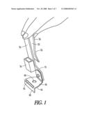
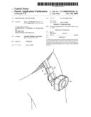
[0005]FIG. 1 shows a perspective view of a tape measure holder according to one embodiment.
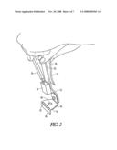
[0006]FIG. 2 shows another view of the tape measure holder of FIG. 1.
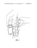
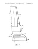
[0007]FIG. 3 shows a side view of the tape measure holder of FIG. 1.
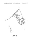
[0008]FIG. 4 shows a perspective view of the tape measure holder of FIG. 1.
[0009]FIG. 5 shows a perspective view of a tape measure holder according to one embodiment.
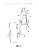
[0010]FIG. 6 shows a perspective view of a tape measure holder according to one embodiment.
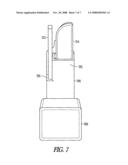
[0011]FIG. 7 shows a front view of the tape measure holder of FIG. 6.
DETAILED DESCRIPTION
[0012]In the following detailed description, reference is made to the accompanying drawings which form a part hereof, and in which is shown by way of illustration specific embodiments in which the invention may be practiced. These embodiments are described in sufficient detail to enable those skilled in the art to practice the invention, and it is to be understood that the embodiments may be combined or that other embodiments may be utilized and that structural changes may be made without departing from the spirit and scope of the present invention. The following detailed description is, therefore, not to be taken in a limiting sense, and the scope of the present invention is defined by the appended claims and their equivalents.
[0013]FIGS. 1-4 show a tape measure holder 10, according to one embodiment of the present invention. Tape measure holder 10 is a tape measure accessory which attaches to the user's belt 15, enabling the quick removal and replacement of a tape measure 20, and also providing storage for a carpenter's or regular pencil 25.
[0014]As noted above, most tape measures have a belt clip 21 to enable the user to attach the tape measure to the belt. These clips 21 generally include a tight spring action which often requires the user to use two hands to attach the clip to their belt.
[0015]Tape measure holder 10 includes an upper portion 30 including an attaching section such as clip 32 to attach to a belt 15. Tape measure holder also includes a lower portion 40 connected to upper portion 30. Lower portion 30 is substantially rigid and includes a slot 42 to receive clip 21 of the tape measure 20.
[0016]In one example, clip 32 includes a generally U-shaped member including a first wall 33 and a second wall 35 separated by a gap. Clip 32 is placed over a belt or the top of a user's pants with first wall 33 inside the belt and second wall 35 outside the belt. Upper portion 30 can be molded from plastic, for example.
[0017]Lower portion 40 is substantially rigid. For example, lower portion 40 can be formed of a metal. In this example, lower portion 40 includes an upper wall or shelf 44 that extends perpendicular from upper portion 30. A lip 46 extends down from shelf 44 and slot 42 is located close to or at the junction of shelf 44 and lip 46.
[0018]The clip 21 of the tape measure easily slides into slot 42 due to the rigidity of the metal of lower portion 40, and is also easily removed.
[0019]In this example, a pencil holder 34 is attached to upper portion 30, in which to slide a carpenter's or regular pencil 25 for storage. The shelf or top section 44 of the lower portion 40 also can include a small hole 48, which serves to contain the bottom of the pencil without damaging the tip.
[0020]FIG. 5 shows a perspective view of a tape measure holder 200 according to one embodiment. In this example, tape measure holder includes an upper portion 202 including a clip 206 for attaching to a user's belt, such as discussed above. In this embodiment, lower portion 208 is a substantially rigid member made of metal for example. An upper wall 210 of lower portion 208 extends at about a 45 degree angle from upper portion 202. A lip 208 extends down from upper wall 210 and a slot 212 is formed close to or at the junction between upper wall 210 and lip 208. A pencil holder 204 is attached to upper portion 202 and a hole or slot 214 is provided to receive a tip of the pencil. The 45 degree angle of upper wall 210 provides for easier placing and removing of a tape measure, for some models of tape measure.
[0021]FIGS. 6 and 7 show a perspective view and a front view, respectively, of a tape measure holder 300, according to one embodiment. Tape measure holder 300 includes an upper portion 302 including a clip 304 for attaching to a user's belt, such as discussed above. In this embodiment, lower portion 306 is a substantially rigid member made of metal for example, and includes a slot 308 to receive a clip of a tape measure 309, such as discussed above.
[0022]In this example, holder 300 includes a pencil holder 320 attached to upper portion 302 for holding a pencil 312, and a utility knife holder 322 attached to upper portion 302 for holding a utility knife 314. In this example, the pencil holder 320 and utility knife holder 310 are molded as a unitary unit with the rest of upper portion 302. A spring clip can be incorporated within utility knife holder 322 to help hold the utility knife in place.
[0023]The above description is intended to be illustrative, and not restrictive. Many other embodiments will be apparent to those of skill in the art upon reviewing the above description. The scope of the invention should, therefore, be determined with reference to the appended claims, along with the full scope of equivalents to which such claims are entitled.
User Contributions:
comments("1"); ?> comment_form("1"); ?>Inventors list |
Agents list |
Assignees list |
List by place |
Classification tree browser |
Top 100 Inventors |
Top 100 Agents |
Top 100 Assignees |
Usenet FAQ Index |
Documents |
Other FAQs |
User Contributions:
Comment about this patent or add new information about this topic:
| People who visited this patent also read: | |
| Patent application number | Title |
|---|---|
| 20150050920 | URGENT CALL-BACK FEATURE THAT LOCKS-OUT NON-URGENT CALLS |
| 20150050919 | MOBILE COMMUNICATION TERMINAL FOR PTT AND METHOD FOR PROCESSING MISSED CALL INFORMATION THEREOF |
| 20150050918 | SYSTEMS AND METHODS FOR CONTROLLING DEVICE NETWORK ACCESS THROUGH A WIRELESS ROUTER |
| 20150050917 | METHOD FOR ENSURING SECURITY AND PRIVACY IN A WIRELESS COGNITIVE NETWORK |
| 20150050916 | ABOVE-LOCK CAMERA ACCESS |
Images included with this patent application:
 |  |
 |  |
 |  |
 |  |
| Similar patent applications: | |
| Date | Title |
|---|---|
| 2012-12-27 | Cup holder for the visually impaired |
| 2011-10-13 | Holder for sunglasses or eyewear |
| 2012-10-11 | Universal holder for a firearm |
| 2010-06-17 | Holder for items |
| 2012-07-26 | Accessory holder for handlebars |
| New patent applications in this class: | |
| Date | Title |
|---|---|
| 2016-05-26 | Gun sling retaining device |
| 2016-02-25 | Belt hanger for handheld device |
| 2016-02-25 | Hydration spin belt |
| 2016-02-11 | Concealed carry clip for handguns |
| 2015-12-10 | Tool holder |
| Top Inventors for class "Package and article carriers" | |
| Rank | Inventor's name |
|---|---|
| 1 | Chris Sautter |
| 2 | Zac Elder |
| 3 | Peter Douglas Hubbard |
| 4 | Douglas Harland Murdoch |
| 5 | Jeffrey M. Aftanas |