Patent application title: Inkjet Printhead Assembly
Inventors:
Kia Silverbrook (Balmain, AU)
IPC8 Class: AB41J214FI
USPC Class:
347 54
Class name: Ink jet ejector mechanism (i.e., print head) drop-on-demand
Publication date: 2009-03-12
Patent application number: 20090066760
Inventors list |
Agents list |
Assignees list |
List by place |
Classification tree browser |
Top 100 Inventors |
Top 100 Agents |
Top 100 Assignees |
Usenet FAQ Index |
Documents |
Other FAQs |
Patent application title: Inkjet Printhead Assembly
Inventors:
Kia Silverbrook
Agents:
SILVERBROOK RESEARCH PTY LTD
Assignees:
Origin: BALMAIN, AU
IPC8 Class: AB41J214FI
USPC Class:
347 54
Abstract:
A printhead assembly is disclosed. The printhead assembly comprises a
printhead formed from a silicon substrate, and a support member. The
support member comprises a core element defining a plurality of ink
reservoirs and a multilayer shell. Each ink reservoir is in fluid
communication with the printhead. The multilayer shell is formed around
at least part of the core element, and has an effective coefficient of
thermal expansion which is comparable to that of silicon.Claims:
1. A printhead assembly comprising:a printhead formed from a silicon
substrate; anda support member comprising:a core element defining a
plurality of ink reservoirs, each ink reservoir being in fluid
communication with the printhead; anda multilayer shell formed around at
least part of the core element, the multilayer shell having an effective
coefficient of thermal expansion which is comparable to that of silicon.
2. A printhead assembly as claimed in claim 1, wherein the multilayer shell is formed from a plurality of layers of metals, each of the layers having a coefficient of thermal expansion which is different to that of silicon.
3. A printhead assembly as claimed in claim 1, wherein the printhead comprises a moulding bonded to the core element and a silicon printhead integrated circuit, the moulding defining a plurality of ink passages for passing ink from the ink reservoirs to the printhead integrated circuit.
4. A printhead assembly as claimed in claim 1, wherein the multilayer shell comprises a triplet of metal layers, one of the layers having a first coefficient of thermal expansion and is located between a pair of layers each having a second coefficient of thermal expansion.
5. A printhead assembly as claimed in claim 4, wherein the first coefficient of thermal expansion is greater than the second coefficient of thermal expansion.
6. A printhead assembly as claimed in claim 5, wherein the second coefficient of thermal expansion is about 1.3.times.10.sup.-6 m/° C.
7. A printhead assembly as claimed in claim 5, wherein the first coefficient of thermal expansion exceeds 2.5.times.10.sup.-6 m/° C.
Description:
CROSS REFERENCE TO RELATED APPLICATION
[0001]The present application is a continuation of U.S. application Ser. No. 11/583,937 filed on Oct. 20, 2006, which is a continuation of U.S. application Ser. No. 11/144,803 filed on Jun. 6, 2005 now issued as U.S. Pat. No. 7,140,718, which is a continuation of U.S. application Ser. No. 10/882,768 filed Jul. 2, 2004, now issued as U.S. Pat. No. 6,959,975 which is a continuation of U.S. application Ser. No. 10/713,089 filed Nov. 17, 2003, now issued as U.S. Pat. No. 6,799,836, which is a continuation of U.S. application Ser. No. 10/129,503 filed May 6, 2002, now issued as U.S. Pat. No. 6,676,245, which is a 371 of PCT/AU01/00239 filed on Mar. 6, 2001, all of which are herein incorporated by reference.
FIELD OF THE INVENTION
[0002]The present invention relates to printers, and in particular to digital inkjet printers.
CO-PENDING APPLICATIONS
[0003]Various methods, systems and apparatus relating to the present invention are disclosed in the following co-pending applications filed by the applicant or assignee of the present invention on 24 May 2000:
TABLE-US-00001 PCT/AU00/00578 PCT/AU00/00579 PCT/AU00/00581 PCT/AU00/00580 PCT/AU00/00582 PCT/AU00/00587 PCT/AU00/00588 PCT/AU00/00589 PCT/AU00/00583 PCT/AU00/00593 PCT/AU00/00590 PCT/AU00/00591 PCT/AU00/00592 PCT/AU00/00584 PCT/AU00/00585 PCT/AU00/00586 PCT/AU00/00594 PCT/AU00/00595 PCT/AU00/00596 PCT/AU00/00597 PCT/AU00/00598 PCT/AU00/00516 PCT/AU00/00517 PCT/AU00/00511
[0004]Various methods, systems and apparatus relating to the present invention are disclosed in the following co-pending application, PCT/AU00/01445 filed by the applicant or assignee of the present invention on 27 Nov. 2000. The disclosures of these co-pending applications are incorporated herein by cross-reference. Also incorporated by cross-reference, is the disclosure of a co-filed PCT application, PCT/AU01/00238 (deriving priority from Australian Provisional Patent Application No. PQ6059).
BACKGROUND OF THE INVENTION
[0005]Recently, inkjet printers have been developed which use printheads manufactured by micro-electro mechanical system(s) (MEMS) techniques. Such printheads have arrays of microscopic ink ejector nozzles formed in a silicon chip using MEMS manufacturing techniques.
[0006]Printheads of this type are well suited for use in pagewidth printers. Pagewidth printers have stationary printheads that extend the width of the page to increase printing speeds. Pagewidth printheads do not traverse back and forth across the page like conventional inkjet printheads, which allows the paper to be fed past the printhead more quickly.
[0007]To reduce production and operating costs, the printheads are made up of separate printhead modules mounted adjacent each other on a support beam in the printer. To ensure that there are no gaps or overlaps in the printing produced by adjacent printhead modules it is necessary to accurately align the modules after they have been mounted to the support beam. Once aligned, the printing from each module precisely abuts the printing from adjacent modules.
[0008]Unfortunately, the alignment of the printhead modules at ambient temperature will change when the support beam expands as it heats up during printhead operation. Furthermore, if the printhead modules are accurately aligned when the support beam is at the equilibrium operating temperature, there may be unacceptable misalignments in any printing before the beam has reached the operating temperature. Even if the printhead is not modularized, thereby making the alignment problem irrelevant, the support beam and printhead may bow because of different thermal expansion characteristics. Bowing across the lateral dimension of the support beam does little to affect the operation of the printhead. However, as the length of the beam is its major dimension, longitudinal bowing is more significant and can affect print quality.
SUMMARY OF THE INVENTION
[0009]According to an aspect of the present invention there is provided a printhead assembly comprising:
[0010]a printhead formed from a silicon substrate; and
[0011]a support member comprising: [0012]a core element defining a plurality of ink reservoirs, each ink reservoir being in fluid communication with the printhead; and [0013]a multilayer shell formed around at least part of the core element, the multilayer shell having an effective coefficient of thermal expansion which is comparable to that of silicon.
[0014]Other aspects are also disclosed.
[0015]In some embodiments, the printhead is a plurality of printhead modules positioned end to end along the beam.
BRIEF DESCRIPTION OF THE DRAWINGS
[0016]A preferred embodiment of the invention will now be described, by way of example only, with reference to the accompanying drawing in which:
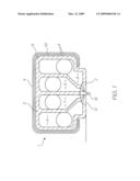
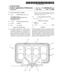
[0017]FIG. 1 is a schematic cross section of a printhead assembly according to the present invention.
DETAILED DESCRIPTION OF THE PREFERRED EMBODIMENTS
[0018]Referring to the FIGURE, the printhead assembly 1 includes a printhead 2 mounted to a support member 3. The support member 3 has an outer shell 4 and a core element 5 defining four separate ink reservoirs 6, 7, 8 and 9. The outer shell 4 is a hot rolled trilayer laminate of two different metals. The first metal layer 10 is sandwiched between layers of the second metal 11. The metals forming the trilayer shell are selected such that the effective coefficient of thermal expansion of the shell as a whole is substantially equal to that of silicon even though the coefficients of the core and the individual metals may significantly differ from that of silicon. Provided that the core or one of the metals has a coefficient of thermal expansion greater than that of silicon, and another has a coefficient less than that of silicon, the effective coefficient can be made to match that of silicon by using different layer thicknesses in the laminate.
[0019]Typically, the outer layers 11 are made of invar which has a coefficient of thermal expansion of 1.3×10⁻⁶ m/° C. The coefficient of thermal expansion of silicon is about 2.5×10⁻⁶ m/° C. and therefore the central layer must have a coefficient greater than this to give the support beam an overall effective coefficient substantially the same as silicon.
[0020]The printhead 2 includes a micro moulding 12 that is bonded to the core element 5. A silicon printhead chip 13 constructed using MEMS techniques provides the ink nozzles, chambers and actuators.
[0021]As the effective coefficient of thermal expansion of the support beam is substantially equal to that of the silicon printhead chip, the distortions in the printhead assembly will be minimized as it heats up to operational temperature. Accordingly, if the assembly includes a plurality of aligned printhead modules, the alignment between modules will not change significantly. Furthermore, as the laminated structure of the outer shell is symmetrical in the sense that different metals are symmetrically disposed around a central layer, there is no tendency of the shell to bow because of greater expansion or contraction of any one metal in the laminar structure. Of course, a non-symmetrical laminar structure could also be prevented from bowing by careful design of the lateral cross section of the shell.
[0022]The invention has been described herein by way of example only. Skilled workers in this field will readily recognise that the invention may be embodied in many other forms.
User Contributions:
comments("1"); ?> comment_form("1"); ?>Inventors list |
Agents list |
Assignees list |
List by place |
Classification tree browser |
Top 100 Inventors |
Top 100 Agents |
Top 100 Assignees |
Usenet FAQ Index |
Documents |
Other FAQs |
User Contributions:
Comment about this patent or add new information about this topic:
Images included with this patent application:
 |  |
| Similar patent applications: | |
| Date | Title |
|---|---|
| 2010-09-23 | Ink jet printer head assembly |
| 2011-07-28 | Inkjet print head assembly and ink supply method thereof |
| 2011-02-03 | Inkjet head and inkjet head assembly |
| 2009-07-09 | Inkjet printer assembly |
| 2013-01-10 | Printer having printer head adjustment assembly |
| New patent applications in this class: | |
| Date | Title |
|---|---|
| 2018-01-25 | Raised fluid pass-through structure in print heads |
| 2016-07-07 | An improved actuator for a printhead |
| 2016-06-30 | Valve jet printer with inert plunger tip |
| 2016-06-23 | Liquid ejecting head and liquid ejecting apparatus |
| 2016-06-09 | Liquid discharge head, liquid discharge apparatus, and method of manufacturing liquid discharge head |
| New patent applications from these inventors: | |
| Date | Title |
|---|---|
| 2017-06-15 | Inkjet printhead assembly having ink and air passages |
| 2017-05-18 | Inkjet printhead assembly having printhead chip carriers received in slot |
| 2016-06-09 | Inkjet printer having ink distribution stack for receiving ink from ink ducting structure |
| 2015-11-26 | Inkjet printhead assembly including slotted shield plate |
| 2015-07-16 | Method of wiping pagewidth printhead |
| Top Inventors for class "Incremental printing of symbolic information" | |
| Rank | Inventor's name |
|---|---|
| 1 | Kia Silverbrook |
| 2 | Akira Nakazawa |
| 3 | Garry Raymond Jackson |
| 4 | Christopher Hibbard |
| 5 | Norman Micheal Berry |