Patent application title: Vehicle Crane with a Bogie and a Superstructure
Inventors:
Frank Wernicke (Contwig, DE)
Jürgen Appel (Contwig, DE)
Jürgen Appel (Contwig, DE)
Christian Fuhrmeister (Homburg, DE)
Ascan Klein (Kashofen, DE)
Assignees:
TEREX DEMAG GMBH
IPC8 Class: AB66C2340FI
USPC Class:
212172
Class name: Traversing hoists having clutch or variable speed transmission power takeoff
Publication date: 2010-03-04
Patent application number: 20100051570
Inventors list |
Agents list |
Assignees list |
List by place |
Classification tree browser |
Top 100 Inventors |
Top 100 Agents |
Top 100 Assignees |
Usenet FAQ Index |
Documents |
Other FAQs |
Patent application title: Vehicle Crane with a Bogie and a Superstructure
Inventors:
Jurgen Appel
Frank Wernicke
Christian Fuhrmeister
Ascan Klein
Agents:
COHEN, PONTANI, LIEBERMAN & PAVANE LLP
Assignees:
Terex Demag GmbH
Origin: NEW YORK, NY US
IPC8 Class: AB66C2340FI
USPC Class:
212172
Patent application number: 20100051570
Abstract:
The vehicle crane comprises a truck carrier and a superstructure in which
the driving of the superstructure function is carried out by means of
hydraulic pumps in the truck carrier, and the hydraulic pumps are driven
by a distributor gear unit which is arranged in the truck carrier and to
which the output shaft of the vehicle drive is connected.Claims:
1-6. (canceled)
7. A vehicle crane comprising a truck carrier (1) including a vehicle drive (3,4);a superstructure (2) above said truck carrier;a distributor gear unit (6) arranged in the truck carrier for connecting an output shaft of said vehicle drive (3,4); anda hydraulic pump (7) disposed in the truck carrier for driving superstructure functions, said hydraulic pump being driven by said distributor gear unit.
8. The vehicle crane according to claim 1, additionally comprising a pump drive (6b) and a distributor gear unit output (6a) and wherein said distributor gear unit (6) has a neutral position toward said distributor gear unit output (6a) and a clutch for engaging and disengaging said pump drive (6b).
9. The vehicle crane according to claim 1, additionally comprising one or more gear reductions of the vehicle drive (4) for limiting the speed of the engine (3) in superstructure operation.
10. The vehicle crane according to claim 3, wherein in said gear reductions are changeable under load.
11. The vehicle crane according to claim 1, wherein said hydraulic pump (7) arranged at the distributor gear unit (6) serves an auxiliary vehicle brake.
12. The vehicle crane according to claim 1, additionally comprising a drive shaft (5) and wherein said distributor gear unit (6) is one of driven by said vehicle drive (4) by means of said driveshaft (5) and is flanged directly to said vehicle drive.
Description:
CROSS REFERENCE TO RELATED APPLICATIONS
[0001]This is a U.S. national stage of application No. PCT/DE2008/000457, filed on 13 Mar. 2008. Priority is claimed on the following application(s): Country: Germany, Application No.: 10 2007 014 943.5, Filed: 23 Mar. 2007, the content of which is incorporated here by reference.
PRIORITY CLAIM
[0002]1. Field of the Invention
[0003]The invention is directed to a vehicle crane having a truck carrier and a superstructure.
[0004]2. Background of the Invention
[0005]Drives of hydraulic pumps are known in cranes, excavators or other construction machinery and utility vehicles. The pumps which are needed for the various work operations are located at auxiliary drives of engines or vehicle transmissions.
[0006]Further, emergency steering pumps which are operated by auxiliary gear unit drives or auxiliary drive distributor gear units and which ensure the steering function in the respective vehicle in case of steering failure are also known.
[0007]With regard to the power source for the hydraulic pumps, a distinction is made in the field of vehicle cranes between single-engine cranes and dual-engine cranes.
[0008]In single-engine cranes, the pumps needed for superstructure operation are driven by the truck carrier engine which is also used for all truck carrier functions.
[0009]In dual-engine cranes, the truck carrier engine is responsible for the truck carrier functions and the superstructure engine is responsible for the superstructure functions.
[0010]Power takeoffs that have been used up to the present time often have limitations depending on the construction type with respect to the maximum decrease in torque and with respect to gear ratio steps. Further, diverse additional component parts are required for producing the power takeoff function.
SUMMARY OF THE INVENTION
[0011]It is an object of the present invention to provide a vehicle crane which is designed as a single-engine crane, wherein the superstructure hydraulic pump drive makes use of the full torque of the drive motor and the gear ratio of the truck carrier transmission.
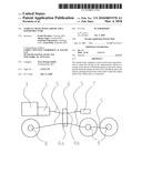
[0012]This object is met according to the present invention by a vehicle crane with a truck carrier and a superstructure in which the driving of the superstructure functions is carried out by means of hydraulic pumps in the truck carrier, and wherein the hydraulic pumps are driven by a transfer case or distributor gear unit which is arranged in the truck carrier and to which the output shaft of the vehicle drive is connected.
[0013]The distributor gear unit has a drive position and a neutral position toward the distributor gear unit output and a clutch for engaging and disengaging the pump drive.
[0014]The hydraulic pumps are driven for superstructure operation by a power takeoff of the truck carrier distributor gear unit.
[0015]The distributor gear unit is driven either by the drive transmission by means of a driveshaft or is flanged directly to the drive transmission. Accordingly, use of the different transmission gear ratios, creates a pump drive which can be varied in speed and torque.
[0016]Another improvement is the use of the hydraulic pump arranged at the pump drive as an additional vehicle brake (retarder). This is achieved by means of a correspondingly designed hydraulic circuit with an integrated throttle valve. For this purpose, both power takeoffs must be active in the drive operation of the crane and the pump output must be switched on for vehicle braking.
[0017]A number of advantages over known power takeoff solutions are offered by the solution according to the present invention: [0018]use of a smaller quantity of parts [0019]reduced weight [0020]reduced costs [0021]variable speed and torque for the pump drive [0022]possibility of increasing pump outputs [0023]use of the hydraulic pump as an auxiliary vehicle brake (retarder).
BRIEF DESCRIPTION OF THE DRAWINGS
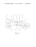
[0024]FIG. 1 is a schematic illustration of the vehicle crane of the present invention;
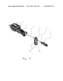
[0025]FIG. 2 is a perspective, schematic view of the engine/transmission arrangement of the present invention; and
[0026]FIG. 3 is a block diagram of the present invention.
DESCRIPTION OF THE PRESENTLY PREFERRED EMBODIMENTS
[0027]Referring more particularly to the drawings, the truck carrier is designated by 1, the superstructure is designated by 2, the truck carrier engine is designated by 3, and the truck carrier transmission is designated by 4.
[0028]The truck carrier transmission (4) is connected to the distributor gear unit (6) by a driveshaft (5).
[0029]The truck carrier engine (3) drives the hydraulic pumps (7) for superstructure operation by means of the truck carrier transmission (4) and the distributor gear unit (6).
[0030]The distributor gear unit (6) has a neutral position toward the distributor gear unit output (6a) and a clutch for engaging and disengaging the pump drive (6b). The axles (8) are driven by the distributor gear unit power takeoff (6a) in drive operation by means of driveshafts (5).
[0031]The drive transmission or truck carrier transmission (4) is shifted into 12th gear in superstructure operation, and the speed of the engine (3) is limited so that it can be used in a user-friendly, torque-optimized range.
[0032]The invention is not limited by the embodiments described above which are presented as examples only but can be modified in various ways within the scope of protection defined by the appended patent claims.
User Contributions:
comments("1"); ?> comment_form("1"); ?>Inventors list |
Agents list |
Assignees list |
List by place |
Classification tree browser |
Top 100 Inventors |
Top 100 Agents |
Top 100 Assignees |
Usenet FAQ Index |
Documents |
Other FAQs |
User Contributions:
Comment about this patent or add new information about this topic:
| People who visited this patent also read: | |
| Patent application number | Title |
|---|---|
| 20100072752 | POWER GENERATION SYSTEM USING HELICAL TURBINE |
| 20100072751 | Variable Speed Wind Turbine, A Resonant Control System, A Method Of Operating A Variable Speed Wind Turbine, Use Of A Resonant Control System And Use Of A Method In A Variable Speed Wind Turbine |
| 20100072750 | Balloonbuddy (A Balloon Tying Tool) |
| 20100072749 | CLAMP COLLAR |
| 20100072748 | COMPRESSION CONNECTION |
Images included with this patent application:
 |  |
 |  |
| Similar patent applications: | |
| Date | Title |
|---|---|
| 2011-02-10 | Lift crane with moveable counterweight |
| 2011-06-09 | Mobile crane with hose guide |
| 2012-11-29 | Crane with overload safety device |
| 2010-08-26 | Rotating superstructure and crane |
| 2012-04-05 | Lattice mast crane and lattice mast boom |
| New patent applications from these inventors: | |
| Date | Title |
|---|---|
| 2015-05-14 | Drive for a sliding connecting member of a locking system of a telescopic system of a crane jib |
| 2011-07-21 | Passively steerable module axle |
| 2011-03-03 | Crane with telescopic boom |
| 2010-10-07 | Auxiliary device for installing the lower and upper jib support of an adjustable auxiliary boom on a mobile crane |
| Top Inventors for class "Traversing hoists" | |
| Rank | Inventor's name |
|---|---|
| 1 | Hans-Dieter Willim |
| 2 | David J. Pech |
| 3 | Klaus Schneider |
| 4 | Robert J. Walker |
| 5 | Oliver Sawodny |