Patent application title: Camera Device Systems and Methods
Inventors:
Chong Ming Gordon Lee (Cambridge, GB)
Geraint James (Baldock, GB)
James D. Bennett (Hroznetin, CZ)
Joseph Hanlim Lee (Foothill Ranch, CA, US)
Assignees:
BROADCOM CORPORATION
IPC8 Class: AH04N5228FI
USPC Class:
3482221
Class name: Television camera, system and detail combined image signal generator and general image signal processing
Publication date: 2013-01-24
Patent application number: 20130021491
Abstract:
Disclosed are various systems and methods implemented in a camera device.
An image sensor is configured to capture image data of a target scene
from a lens system and a subject feedback mechanism generates framing
feedback associated with the image data that includes information about a
current framing of an image associated with the image data. Video capture
logic also obtains motion information from motion sensors integrated into
the camera device and skip frame capture when motion levels exceed a
threshold.Claims:
1. A camera device used within an environment having at least one
surface, the camera device being operable to capture visual content
associated with a target scene that includes at least one human target,
the camera device operating in a hands-free mode, the camera device
comprising: an imager that captures the visual content; a visual frame
indicator; processing circuitry configured to receive a first signal
relating to the visual content captured by the imager; the visual frame
indicator being configured to deliver a visual framing indication for the
human target; and the processing circuitry being configured to respond to
gesture information relating to a gesture of the human target by
delivering a second signal to the visual frame indicator to cause an
adjustment to the visual framing indication, the adjustment corresponding
to a change in a field of view associated with the target scene.
2. The camera device of claim 1, wherein the visual frame indicator delivers the visual framing indication via a projection onto the at least one surface.
3. The camera device of claim 1, wherein the visual framing indication is visible to the human target depending on whether or not the human target is within the target scene.
4. The camera device of claim 1, wherein the visual frame indicator comprises a projector component, and the visual framing indication comprises a visual image corresponding at least in part to the visual content.
5. The camera device of claim 1, wherein the visual framing indication comprises an indication of a frame boundary.
6. The camera device of claim 1, wherein at least one characteristic of the at least one surface of the environment comprises an orientation characteristic relative to that of the visual frame indicator.
7. A processing system used within an environment having at least one surface, the processing system supporting an imager and a visual indicator, the imager being operable to capture visual content associated with a target scene that includes a human target, the processing system comprising: processing circuitry; first interface circuitry that couples the processing circuitry with the imager; second interface circuitry that couples the processing circuitry and the visual indicator; and the processing circuitry configured to deliver at least one control signal to the visual indicator via the second interface circuitry to cause the visual indicator to provide a visual framing indication for the human target.
8. The processing system of claim 7, wherein the first interface circuitry is configured to support receipt by the processing circuitry of a first signal relating to the visual content captured by the imager, and wherein the delivery of the at least one control signal by the processing circuitry to the visual indicator is based at least in part on the first signal received.
9. The processing system of claim 8, wherein the processing circuitry is configured to deliver visual information to the visual indicator, the visual information being adjusted to correspond to an orientation characteristic associated with the at least one surface.
10. The processing system of claim 7, wherein the at least one control signal from the processing circuitry to the visual indicator is configured to direct the visual indicator to provide a visual projection onto the at least one surface.
11. The processing system of claim 7, wherein the at least one control signal from the processing circuitry to the visual indicator is configured to direct the visual indicator to provide a visual indication that is visible to the human target depending on whether or not the human target is within the target scene.
12. The processing system of claim 7, wherein the processing circuitry is further configured to assist in a process of recognizing at least a portion of the human target.
13. The processing system of claim 7, wherein the processing circuitry is further configured to respond to gesture information relating to a gesture of the human target by causing an adjustment to framing of the target scene.
14. A camera device used within an environment having at least one surface, the camera device being operable to capture visual content associated with a target scene that includes at least one human target, the camera device comprising: an imager that captures the visual content associated with the target scene; a visual frame indicator; a lens system having a current configuration; processing circuitry configured to deliver a framing signal to the visual frame indicator; and the visual frame indicator configured to respond to the framing signal by providing a visual framing indication for the human target, the visual framing indication being determined at least in part by the current configuration of the lens system.
15. The camera device of claim 14, wherein the visual frame indicator is configured to deliver the visual framing indication via a projection onto the at least one surface.
16. The camera device of claim 14, wherein the visual framing indication is visible to the human target depending on whether or not the human target is within the target scene.
17. The camera device of claim 14, wherein the processing circuitry is configured to respond to gesture information relating to a gesture by the human target by causing an adjustment to a framing of the visual content associated with the target scene.
18. The camera device of claim 17, wherein the adjustment to the framing of the visual content is implemented via a change to the current configuration of the lens system.
19. The camera device of claim 17, wherein the imager comprises an array of imager elements, the adjustment to the framing of the visual content involving a selection of only a portion of the array of imager elements to construct an image, and the visual framing indication being based at least in part on the selection.
20. The camera device of claim 14, wherein the lens system comprises an adjustable lens assembly.
21. The camera device of claim 14, wherein the lens system is configured to crop at least a portion of the visual content captured by the imager.
Description:
CROSS-REFERENCE TO RELATED APPLICATION
[0001] This application claims priority to co-pending U.S. provisional application entitled, "Image Capture Device Systems and Methods," having Ser. No. 61/509,747, filed Jul. 20, 2011, which is entirely incorporated herein by reference.
BACKGROUND
[0002] Image capture devices (e.g., cameras, camera devices, etc.) can be employed by users to capture one or more images and/or video of various target scenes. Often, a user operating an image capture device may wish to appear in a target scene. In this and other scenarios, when the image capture device is capturing an image in an autonomous and/or timed mode, there is little or no user feedback regarding framing of the image, particularly once the user is positioned within the target scene. Accordingly, the framing conditions of the captured imagery can be less than ideal. A user and/or subject in an image may appear off centered, a portion of the user may be outside of the current or ideal framing of the image, or other occurrences may negatively impact framing of the image. Additionally, an image capture device configured to capture video (e.g., multiple image frames stitched together to form a video), vibration and/or movement of the image capture device can result in the captured video becoming blurred due to the movement of the image capture device.
BRIEF DESCRIPTION OF THE DRAWINGS
[0003] Many aspects of the invention can be better understood with reference to the following drawings. The components in the drawings are not necessarily to scale, emphasis instead being placed upon clearly illustrating the principles of the present invention. Moreover, in the drawings, like reference numerals designate corresponding parts throughout the several views.
[0004] FIGS. 1A-1B are drawings of a camera device according to various embodiments of the disclosure.
[0005] FIG. 2 is a drawing of an alternative camera device according to various embodiments of the disclosure.
[0006] FIG. 3 is a drawing of various components of a camera device of FIGS. 1A-1B and FIG. 2 according to various embodiments of the disclosure.
[0007] FIGS. 4A-4D are drawings of a camera device according to embodiments of the disclosure that provide framing feedback.
[0008] FIGS. 5-8 are drawings of a camera device providing framing feedback according to various embodiments of the disclosure.
[0009] FIG. 9 is a flowchart illustrating one example of video capture logic executed in a camera device illustrated in FIGS. 1A-1B and FIG. 2 according to various embodiments of the disclosure.
DETAILED DESCRIPTION
[0010] Embodiments of the present disclosure relate to systems and methods that can be executed in an image capture device or camera device (e.g., still image capture devices, video cameras, still and video multi-function camera devices, etc.). More specifically, embodiments of the disclosure are directed to providing feedback, or a visual frame indicator, to a subject in a target scene indicating how the camera device is aimed and how the target scene is framed, so that the subject can use this feedback regarding framing conditions and characteristics of one or more images that the camera device is capturing to improve the framing of the target scene. Framing conditions can include, but are not limited to, a location within an image along a vertical and horizontal axis (i.e., two dimensional framing conditions) as well as a depth of field of a subject in the image (i.e., third dimension). Embodiments of the disclosure are also directed to systems and methods in a camera device that can reduce blur in a video captured by the camera device by employing vibration and/or motion sensing capabilities that can be integrated within a camera device.
[0011] A camera device can include or be incorporated within a camera, video camera, a mobile device with an integrated camera device, set top box, game unit, gaming console, web cameras, wireless or wired access points and routers, laptop computer, modems, tablet computers, or any other mobile or stationary devices suitable to capturing imagery and/or video as can be appreciated. In some embodiments, a camera device according to an embodiment of the disclosure can be integrated within a device such as a smartphone, tablet computing system, laptop computer, desktop computer, or any other computing device that has the capability to receive and/or capture imagery via image capture hardware.
[0012] Accordingly, camera device hardware can include components such as lenses, image sensors, or imagers, (e.g., charge coupled devices, CMOS image sensor, etc.), processor(s), image signal processor(s) (e.g., digital signal processor(s)), a main processor, memory, mass storage, or any other hardware, processing circuitry or software components that can facilitate capture of imagery and/or video. In some embodiments, a digital signal processor can be incorporated as a part of a main processor in a camera device module that is in turn incorporated into a device having its own processor, memory and other components.
[0013] A camera device according to an embodiment of the disclosure can provide a user interface via a display that is integrated into the camera device and/or housed independently thereof. The display can be integrated with a mobile device, such as a smartphone and/or tablet computing device, and can include a touchscreen input device (e.g., a capacitive touchscreen, etc.) with which a user may interact with the user interface that is presented thereon. The camera device hardware can also include one or more buttons, dials, toggles, switches, or other input devices with which the user can interact with software or firmware executed in the camera device.
[0014] Referring now to the drawings, FIGS. 1A-1B show a mobile device 102 that can comprise and/or incorporate a camera device according to various embodiments of the disclosure. The mobile device 102 may comprise, for example, a processor-based system, such as a computer system. Such a computer system may be embodied in the form of a desktop computer, a laptop computer, a personal digital assistant, a mobile device (e.g., cellular telephone, smart phone, etc.), tablet computing system, set-top box, music players, or other devices with like capability. The mobile device can include, for example, a camera device 104, which can further include a lens system 108 as well as other hardware components that can be integrated with the device to facilitate image capture. The mobile device 102 can also include a display device 141 upon which various content and other user interfaces may be rendered. The mobile device 102 can also include one or more input devices with which a user can interact with a user interface rendered on the display device 141. For example, the mobile device 102 can include or be in communication with a mouse, touch input device (e.g., capacitive and/or resistive touchscreen incorporated with the display device 141), keyboard, or other input devices.
[0015] The mobile device 102 may be configured to execute various applications, such as a camera application that can interact with an image capture module that includes various hardware and/or software components that facilitate capture and/or storage of images and/or video. In one embodiment, the camera application can interact with application programming interfaces (API's) and/or other software libraries and/or drivers that are provided for the purpose interacting with image capture hardware, such as the lens system and other image capture hardware. The camera application can be a special purpose application, a plug-in or executable library, one or more API's, image control algorithms, camera device firmware, or other software that can facilitate communication with image capture hardware in communication with the mobile device 102. Accordingly, a camera application according to embodiments of the present disclosure can capture imagery and/or video via the various image capture hardware as well as facilitate storage of the captured imagery and/or video in memory and/or mass storage associated with the mobile device 102.
[0016] The mobile device 102 can also include a visual framing indicator 111 that can provide framing feedback to a user positioned in a target scene to which the lens system 108 is pointed. As described herein, framing feedback can take the form of audible and/or visible indicators or cues that a current framing of an image to be determined from a position within or near the target scene to which the lens system 108 is aimed. As described below, the visual framing indicator 111 can take the form of a projection system or projector component (e.g., pico-projector), laser scanner, holographic optical element, LEDs, or any other components that can generate any type of markers, textual information, visual information, and/or video or images that are visible to the user, or visible on a remote surface relative to the camera device 104. Such a surface can include a wall, floor, or any other surface that is within or near a target scene.
[0017] FIG. 2 illustrates an alternative example of a camera device 124 according to an embodiment of the disclosure. Like the camera device 104 in the mobile device 102 of FIGS. 1A-1B, the depicted standalone camera device 124 can also include processing circuitry such as a digital signal processor, memory, and other components that can execute software logic to facilitate the embodiments described herein. The camera device 124 shown in FIG. 2 can also have a visual framing indicator 126 as discussed above with reference to the mobile device 102 of FIGS. 1A-1B to provide feedback regarding framing conditions to a user positioned within or near a target scene. Additionally, the camera device 104 may include a lens system 163 having a fixed focal length or an adjustable focal length (e.g., a zoom lens).
[0018] FIG. 3 illustrates an embodiment of the various image capture components, or one example of a camera device 300 as illustrated in FIGS. 1A-1B and FIG. 2. Although one implementation is shown in FIG. 3 and described herein, a camera device according to an embodiment of the disclosure more generally comprises a camera device that can provide images and/or video in digital form. The camera device 300 includes a lens system 301 that conveys images of viewed scenes to an image sensor 302. By way of example, the image sensor 302 comprises a charge-coupled device (CCD) or a complementary metal oxide semiconductor (CMOS) sensor that is driven by one or more sensor drivers. The analog image signals captured by the sensor 302 are provided to an analog front end 304 for conversion into binary code that can be processed by a controller 308 or processor.
[0019] The controller 308 executes various types of logic that can be available in program memory 310 accessible to the camera device 300 in order to facilitate the functionality described herein. In other words, the controller 308 can place the camera device 300 into various modes, such as a video capture mode that allows a user to capture video. As described herein, the video capture mode also allows video to be captured while detecting motion, vibration, and/or movement associated with the camera device 300 and/or the current framing of a target scene and skip the capture of frames when movement is above a threshold. The controller 308 can also place the camera device 300 into a framing feedback mode that allows a user to capture images and/or video of a target scene while providing visual and/or audible framing feedback to a user position in or near the target scene. The framing feedback mode also allows a user to perform gestures or provide audible commands that are interpreted by the controller to affect framing of a target scene or initiate other operations associated with the camera device 300. The various modes can be selected by the controller 308 manually (e.g., via user input), automatically, and/or semi-automatically. The various modes can also be executed simultaneously by the controller 308.
[0020] Additionally, the controller 308 interacts with various hardware components associated with the camera device 300, such as image sensors, motion sensors, vibration sensors, accelerometers, user input devices, storage media, display devices, serial communication interface(s), and other hardware components as can be appreciated. The controller 308 also allows the camera device 300 to be operated in an autonomous and/or hands-free mode in which a user can initiate image and/or video capture, adjustment of a field of view of a lens system, and/or any other adjustments to the camera device 300 as discussed herein. Additionally, a camera device 300 according to the present disclosure can also include one or more visual and/or audio projection systems that can include emit visible and/or audible feedback to a user. As described herein, these projection systems can include, but are not limited to, one or more lights, light emitting diode(s) (LEDs), laser, holographic optical elements, video projection systems (e.g., pico projector, etc.), speakers, or other devices that can facilitate communication with a user.
[0021] Accordingly, the video capture logic 315 in the program memory 310 is executed by the controller 308 to facilitate a video capture mode that can reduce blur or other video artifacts that result from vibration or other movement of the camera device 300. Upon receiving a command to initiate capture of video from a capture trigger 335, the video capture logic 315 can determine a frame rate associated with the video and capture images from the image sensor 302 at a rate consistent with the frame rate and store the video in a mass storage 341 device accessible to the camera device 104.
[0022] The video capture logic 315 receives motion, movement and/or vibration data from one or more motion sensors 313 that are integrated within the camera device 300. To this end, the video capture logic 315 can include vibration detection logic 316, zooming detection logic 317, tracking detection logic 318, and/or panning detection logic 319, which can detect movement of the camera device 300 as well as movement of the framing of a target scene that is caused by zooming and/or panning of the lens system 301. The motion sensors 313 can include, but are not limited to, motion detectors, accelerometers and/or other devices that can detect movement of the camera device 300. The video capture logic 315 skips capture of a frame associated with the video when movement data from the motion sensor(s) 313 indicates that motion of the camera device 300 and/or motion associated with adjustment of a zoom level and/or panning exceeds a threshold. The video capture logic 315 captures the video frame when movement of the camera device 300 is less than a threshold. The video capture logic 315 can adhere to a requested frame rate by producing an output video having a number of frames per time period consistent with the requested frame rate, but where the video frames may not be evenly spaced because frame capture may be initiated when movement is below a threshold.
[0023] The video capture logic 315 can also adjust the movement threshold so that it is a relative measure of movement during capture of a given video. In this way, the video capture logic 315 can capture video frames over a given time period where the frames are associated with lower levels of movement relative to other portions of the time period. For example, the video capture logic 315 may identify that movement levels associated with the camera device 300 are oscillating. Accordingly, the video capture logic 315 can identify the oscillating pattern and capture video frames when movement levels are at their lowest relative to other portions of a given time period.
[0024] In such a scenario, the video capture logic 315 can also recognize an oscillating pattern in movement from the motion sensor(s) 313 and initiate capture of additional video frames before a peak in movement of the camera device 300 as well as subsequent to the peak so that enough frames are captured according to a requested frame rate. Additionally, because captured frames of the video may be unevenly temporally spaced, the video capture logic 315 can employ video encoding techniques that compensate for such a scenario to reduce the impact on the quality of the resultant captured video. Additionally, the video capture logic 315 can force capture of video frames even if movement of the camera device 300 does not drop below a movement threshold. For example, the video capture logic 315 can force capture of video frames in order to produce an output video possessing an acceptable number of frames per time period according to a requested frame rate.
[0025] The controller 308 also executes framing feedback logic 321 available in the program memory 210 to facilitate a framing feedback mode that provides feedback or a visual framing indicator to a user regarding framing characteristics of an image or video captured (or to be captured) by the camera device 300. The feedback includes feedback that is provided to a human subject in or near a target scene, as the feedback is visible and/or audible from a position within or near the target scene, which may not be a position from which a local display 345 of the camera device 300 is visible. In other words, a user who may be positioned within a target scene to which the lens system 301 is aimed can receive information regarding the current framing of an image, where the information is projected outside of the housing of the camera device 300, and where the information includes framing conditions, zoom levels, lighting conditions, and other framing characteristics.
[0026] In one embodiment, the framing feedback logic 321 can employ a projection-illumination subsystem 323 of the camera device 300 in order to project visual feedback regarding the framing conditions of an image such that it is visible from the target scene. In this way, a subject of an image can determine, by viewing the feedback generated by the camera device 104, whether the framing characteristics of the image to be captured are as the user intended or desires. The projection-illumination subsystem 323 can include projection systems, such as a microelectromechanical (MEMS) pico-projector 324, one or more light emitting diodes, laser systems 326, light source 327, one or more holographic optical elements (HOE) 325, or any other system that can emit a visible light or indicator (e.g., a glowing or fluorescent dot). The projection-illumination subsystem 323 can also include systems that can modify of control the visibility of the various projection systems, such as a fixed slit barrier 329, adaptable slit barrier 330 and/or light source shroud 328.
[0027] As one example of execution of the framing feedback logic 321, the focal region logic 372 determines the current framing or field of view of a target scene as captured by the lens system 301, and cause the laser scanning system 326 projects a frustum of light having a height and width proportional to the image sensor 302 such that the frustum of light illuminates anything that is within the current framing of the image. In other words, the focal region logic 372 causes the projection-illumination subsystem 323 to emit a frustum of light that approximates the field of view of the lens system 301 at any moment in time. In this way, a subject can determine whether he or she is within the current framing of an image by determining whether he or she can see or is within the frustum of light.
[0028] In the case of a camera device 300 having a fixed focal length lens system 301, the HOE 325 is configured to emit a fixed frustum of light that is tuned to approximate the framing of the fixed focal length lens system 301. In the case of an adjustable focal length lens system 301, the MEMS pico-projector 324 and/or laser system 326 that is integrated within the camera device 300 emits a frustum of light and/or a boundary of light that is visible when cast against a background in the target scene that approximates the current framing of the image, or the frame boundary. In this scenario, the focal region logic 372 determines a zoom level associated with the lens system 301 and in turn determines a current framing of the image or field of view of the lens system 301. As another example, the focal region logic 372 can calculate a zoom level from a user input device 331, such as, a zoom input 333 device that allows the user to adjust the focal length of the lens system 301. Accordingly, the focal region logic 372 causes the projection-illumination subsystem 323 to emit a frustum of light corresponding to the current framing of the image.
[0029] Additionally, the focal region logic 372 can also cause the projection-illumination subsystem 323 to emit ground lines or outlines that are cast against the ground and that correspond to the current framing, a rectangular area corresponding to the current framing and/or any other visible indication that approximates the current framing of an image to be captured by the camera device 300.
[0030] The framing feedback logic 321 can also employ the projection-illumination subsystem 323 to project a representation of a viewfinder or display of the camera device 104 such that it is visible from a position in the target scene and outside the housing of the camera device 300. In this way, a user in the target scene can observe the current framing of the image. The display projection logic 376 is executed by the framing feedback logic 321 to cause the projection-illumination subsystem 323 to project the display or viewfinder representation on the ground at a position between the camera device 104 and the target scene, on a background of the target scene, behind the camera device 104 such that the camera device 104 is positioned between the projection and the target scene, and/or at any other surface or position such that is viewable from the target scene. For example, the MEMS pico-projector 324 integrated within the camera device 300 project a representation of the target scene as viewed by the lens system 301 such that it is visible by a subject within the target scene.
[0031] The framing feedback logic 221 can also provide framing feedback or a visual frame indicator in the form of a light source, or other visible source, emitted from the camera device 104. The focal region logic 372 executed by the framing feedback logic 321 employs various mechanisms to control whether a light source 327 (e.g., light emitting diode(s), laser(s), glowing or florescent component, etc.) emits light (or reflected light) that is visible from various positions within or around the target scene. Accordingly, the framing focal region logic 372 adjusts visibility of such a light source 327 such that it is visible from a position within the current framing of the image. The focal region logic 372 disables visibility of the light source 327 from a position that is outside the current framing of the image. As one example, the projection-illumination subsystem 323 employs a light source shroud 328, a fixed slit barrier 329 and/or adjustable slit barrier 330 that limits the viewing angles from which the light source 327 is visible so that a subject can look at the camera device 300 and determine whether he or she is in the current framing or field of view of the lens system 301 based upon whether he or she can see the light source.
[0032] The focal region logic 372 can also determine a field of view of the lens system 301 based upon a zoom level of the lens system 301 and adjust visibility using these various mechanisms as the zoom level of the lens system 301 is adjusted. For example, the focal region logic 372 can adjust visibility of the light source 327 as the zoom level is adjusted so that a viewing angle from which the light source 327 is visible from the target scene increases as the zoom level decreases, and where the viewing angle decreases as the zoom level increases. It should also be appreciated that embodiments of the disclosure can be configured such that the light source 327 is visible from a position outside the target scene and adjusted such that the light source 327 is not visible from a position inside the target scene.
[0033] In one embodiment, the focal region logic 372 can position a visible indicator of the current framing of an image by generating ground lines emitted by the laser system 326 and/or the MEMS pico-projector 324 such that they are initially visible within the frame. For example, focal region logic 372 can cause the laser scanning system 326 to emit lines corresponding to left and right ground lines such that they are visible on the ground via the lens system 301. Upon detecting the existence of the visible ground lines, the focal region logic 372 can increase the angle of the left and right ground lines relative to one another until the ground lines are subsequently not visible, which translates into the ground lines being positioned just outside the current framing of the image. Accordingly, a subject can position himself or herself within the ground lines upon their final positioning by the focal region logic 372 and know that he or she is within the current framing of the image.
[0034] In the context of the present disclosure, the MEMS pico-projector 324, adaptable light source 327, HOE 325, and laser scanning system 326 can provide framing feedback that is visible outside a housing of the camera device 300 (e.g., light projected on the ground, background, or any other surface outside the camera device 300 housing that is visible from the targets scene). In contrast, the light source 327 operates in conjunction with the light source shroud 328, the fixed slit barrier 329 and/or adaptable slit barrier 330 within the camera device 300 housing to enable or disable visibility of the light source 327 from various viewing angles outside of the housing.
[0035] The framing feedback logic 221 can also execute audible feedback logic 375 to identify subjects in a target scene and cause a speaker system integrated within the camera device 300 to emit audible feedback regarding the current framing of an image. The audible feedback can provide a subject in a target scene with information regarding the current framing of an image. For example, the audible feedback logic 375 can recognize faces, bodies or other objects in a target and determine whether the framing of the image can be improved. For example, the audible feedback logic 375 can determine whether faces, bodies, and/or objects are centered within the current framing of the image and generate audible feedback via speech synthesis logic directing a user how faces, bodies, and/or objects should be moved within the current framing of the image.
[0036] In one embodiment, among others, the audible feedback logic 375 can employ speech synthesis logic to instruct a subject within a current framing of the image a direction in which to move to appear centered within the current framing. As an additional example, the audible feedback logic 375 can also emit an audible message informing a subject in the target scene of when an image is to be captured. For example, the audible feedback logic 375 employs speech synthesis logic 388 to generate a voice countdown to so that a user is aware of when an image and/or video is going to be captured by the camera device 104.
[0037] The framing feedback logic 221 also executes automated framing and cropping logic 377 that facilitates automated framing and cropping of a target scene based upon identification of faces, bodies, and/or objects within the target scene. For example, the camera device 104 can be placed in a mode by the user that includes automatic image capture of a target scene, perhaps a target scene in which the user is positioned. Accordingly, the face-body-object detection logic 374 executed by the framing feedback logic 221 identifies the presence of one or more faces and/or bodies in the image and the automated framing and cropping logic 377 adjusts framing of an image captured by the image sensor 302 such that the identified faces and/or bodies are substantially centered within the current framing of the image.
[0038] The framing feedback logic 221 also executes gesture recognition logic 385 that allows a user to control the camera device 300 via user input that can be detected while the user is in or near a target scene to which the lens system 301 is pointed. For example, by performing a gesture with a hand and/or arm, a user can adjust a zoom level, focus point, flash controls, and other aspects related to capture of an image by the camera device 300 as can be appreciated. Gestures that a user in a target scene can perform can be linked to actions that can be taken by the gesture recognition logic 385 to perform an action and/or alter characteristics of the camera device 300. The gesture recognition logic 385 can also identify bodies appearing in a target scene to which the lens system 301 is aimed and track the corresponding body parts appearing in the scene. In one embodiment, the gesture recognition logic 385 can employ time of flight camera methods to determine and track a position of a hand and/or arm within a target scene. When a gesture linked to an action is recognized by the gesture recognition logic 385, the gesture recognition logic 385 performs the action in the camera device 300.
[0039] As one example, a user in a target scene can perform a gesture identifying a focus point within the current framing of an image. For example, a user in the target scene can point at a specific area in the target scene for a predetermined amount of time. Accordingly, the gesture recognition logic 385 can cause the controller 308 to identify the area as the focus point in the image, which in turn causes the lens system 301 to focus on the area. As another example, the user can perform a gesture linked to initiating image or video capture (i.e., a "capture trigger" gesture). Such a gesture can comprise a user simulating pulling down on an object, pressing a button, a "thumbs up" hand signal, or any other gesture motion that can be recognized as can be appreciated. Such a gesture can also comprise recognizing when the subjects in the target scene have placed their arms by their side or in a still or ready position. Upon recognizing such a gesture, the gesture recognition logic 385 can, in some embodiments, initiate capture of an image after a predetermined delay or countdown. The gesture recognition logic 385 can also employ other portions of the framing feedback logic 321 to emit feedback to the user so that the user can be aware of the moment that the image and/or video will be captured by the camera device 300.
[0040] As another example of a gesture that can be recognized by the gesture recognition logic 385, the user can also communicate a desired framing of the image via gestures. For example, the user can instruct the gesture recognition logic 385 to frame the image such that the entire body of the user is captured by, for example, pointing at the ground beneath the feet of the user with one hand, indicating a desire for the user to have his or her feet within the framing of the image, and pointing to the head of the user with another hand. As another example, a user can, in a group shot, identify the subjects in a target scene that the user wishes to be present in a resultant framing of an image. In response, the gesture recognition logic 385 can cause the face-object-body framing logic 374 to adjust cropping of a resultant image and/or a zoom level of a lens system 301 to appropriately frame the image and/or video as requested by the user.
[0041] A user can also affect flash settings by performing a gesture that the gesture recognition logic 385 can recognize. For example, a user can toggle a flash between an off-setting, an on-setting, and an automatic setting by performing a gesture linked to modifying flash settings, which the gesture recognition logic 385 can recognize and modify accordingly. The controller 308 can also execute voice recognition logic 386, which allows the user to speak commands that can be linked to various actions as with the gesture recognition logic 385. The voice recognition logic 386 can allow a user to initiate capture of an image or video, specify whether the camera device 104 should capture one of image or video as well as modify framing, focus point, and flash settings as described with reference to the gesture recognition logic 385.
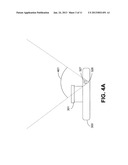
[0042] FIG. 4A illustrates one example of a camera device 300 operating in a mode that provides framing feedback to a subject regarding a current framing of an image. In the depicted example, the camera device 300 is configured with a projection-illumination subsystem 323 that includes a light source 327 as well as a light source shroud 328 configured to modify a viewing angle 401 from which the light source is viewable. In the embodiment of FIGS. 4A and 4B, the framing focal region logic 372 identifies a current framing of a target scene to which the lens system 301 is aimed, or an amount of a target scene in the current framing of an image. The focal region logic 372 specifies a viewing angle 401 at which the light source 327 should be visible such that it is visible from a position within the current framing and not visible from a position outside the current framing. Accordingly, the focal region logic 372 can then adjust the light source shroud 328 such that the viewing angle from which the light source 327 is visible corresponds to the current framing of the image.
[0043] FIG. 4B continues the example of FIG. 4A and illustrates how the focal region logic 372 can adjust the viewing angle 501 at which the light source 327 can be viewed. As noted above, the focal region logic 372 can determine a zoom level associated with an adjustable focal length lens system 301 to determine a current framing of the image. Based upon the current framing of the image, the light source shroud 328 is configured to increase the viewing angle 501 when the zoom level of the lens system 301 is decreased (i.e. "zooming out") and to decrease the viewing angle 501 when the zoom level of the lens system 211 is increased (i.e. "zooming in").
[0044] Reference is now made to FIG. 4C, which illustrates another example of a camera device 300 according to an embodiment of the disclosure. In the depicted example, the camera device 300 employs a fixed slit barrier 329 that includes a light source 327 such as an LED array 402 that is positioned behind a fixed barrier 404. In one embodiment, the LED array 402 comprises a linear array of a plurality of LED's positioned behind the fixed barrier 404 relative to a target scene such that the fixed barrier 404 limits the visibility of the LED array 402 from certain viewing angles. In the depicted embodiment, the fixed barrier 404 provides a slit through which light emanating from the LED array 402 can pass.
[0045] The focal region logic 329 can activate a certain number of LED's in the LED array 404 that causes light to emanate through the fixed barrier 402 such that the light is visible at a viewing angle that corresponds to the field of view of the lens system 301. In other words, if the zoom level of the lens system 301 is modified, the focal region logic 329 can activate an appropriate number of LED's from the LED array 404 that are laterally offset from the slit in the fixed barrier 402 such that they are visible by a subject 461a at a viewing angle in the target scene that corresponds to an angle relative to the lens system 301 that corresponds to the current field of view. As the zoom level of the lens system 301 is changed, it follows that the field of view or current framing correspondingly changes. Accordingly, the focal region logic 329 can activate and/or disable LED's in the LED array 404 as the zoom level of the lens system 301 changes such that it is visible by a subject 461a within the field of view of the lens system 301 but not visible by a subject 461b positioned outside the field of view.
[0046] In the depicted example, the fixed slit barrier 329 is also configured to allow light emanating from the LED array 404 to be visible at a viewing angle that is slightly less than a current field of view of the lens system 301. In other words, the fixed slit barrier 329 introduces a field of view reduction 481a, 481b on opposing sides of the field of view such that the viewing angle of the LED array 404 is less than an angle of the field of view of the lens system 301. This field of view reduction 481a, 481b can be chosen such that it is sized similarly to an average lateral distance between a human subject's eyes and shoulders. The field of view reduction 481a, 481b is introduced so that a user (e.g., subject 461c) cannot see light emanating from the LED array 404 when a portion of the subject 461c that is laterally offset from the subject's 461c eyes are outside the field of view of the lens system 301 even though the subject's 461c face, and therefore eyes, may be within the field of view. Therefore, the LED array 404 is configured to activate LED's such that light emanating through the fixed barrier 402 is generally visible to the subject 461c when the subject's entire body is within the field of view of the lens system 301.
[0047] Reference is now made to FIG. 4D, which illustrates an example of a camera device 300 employing an adaptable slit barrier 330 to emanate light from a light source 328 such as a fixed LED source 493 such that the light is visible within the field of view of the lens system 301. The adaptable slit barrier 330 employs an adaptable barrier 491 that can adjust an aperture through which light from the fixed LED source 493 passes to adjust the viewing angle from the target scene of the light. As in the example of FIG. 4C, the In the example of FIG. 4D can emanate light such that there is a field of view reduction 481a, 481b so that the viewing angle of the light emanating from the adaptable slit barrier 330 is less than the field of view of the lens system 301.
[0048] The adaptable slit barrier 330 can employ techniques similar to those described in U.S. patent application Ser. No. 12/845,409, entitled "Display with Adaptable Parallax Barrier," filed Jul. 28, 2010 (the '409 application), which is hereby incorporated herein by reference in its entirety. More specifically, the adaptable barrier 491 can comprise a linear barrier element array as disclosed in the '409 application comprising a plurality of barrier elements, each of which being selectable to be substantially opaque or transparent. Accordingly, as the field of view of the lens system 301 changes, the focal region logic 372 can select some of the barrier elements in the linear barrier element array that are laterally offset from the center of the barrier 491 to be transparent. In this way, the adaptable slit battier 330 can allow light from the fixed LED source 493 to emanate through the adaptable barrier 491 and to the target scene such that the fixed LED source 493 is visible at a viewing angle corresponding to the field of view of the lens system 301.
[0049] While the example discussed with reference to FIGS. 4C and 4D includes a linear, or one-dimensional, fixed slit barrier 329 and/or adaptable slit barrier 330, either of these devices can also include an LED array as well as barrier oriented in two dimensions so that the viewing angle light emanating from the LED source can be controlled in both the horizontal and vertical directions. In this way, because the light emanating from the LED source is directed in the case of a rectangular image sensor 302, the fixed slit barrier 329 and/or adaptable slit barrier 330 can limit the viewing angle of the LED source in the horizontal and vertical directions relative to the target scene.
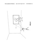
[0050] Reference is now made to FIG. 5, which illustrates an example of a camera device 300 providing framing feedback to a subject 501 in a target scene to which the lens system 301 of the camera device 104 is aimed. In the example of FIG. 5, the focal region logic 372 executed by the controller 308 causes the projection-illumination subsystem 323 to project one or more lines 502a, 502b with a holographic optical element 325, laser system 326, MEMS pico-projector 324 and/or any other mechanism that can project visible lines designating the focal region and/or field of view corresponding to the current framing of the image. These lines 502a, 502b correspond to the edge of the current framing of an image and are visible from the target scene so that a subject 501 can see whether he or she is within the current framing as well as a location within the current framing.
[0051] In one embodiment, the focal region logic 372 can also identify a suggested spot for the subject 501 to position himself within the field of view of the lens system 301 of the camera device 300. The focal region logic 372 can then cause the projection-illumination subsystem 323 to emit an indicator that is cast on the ground in the target scene that provides a suggested position for the subject 501 based on the framing conditions within the field of view of the lens system 301. The suggested position can be based on the size of the subject 501 within the current framing, lighting conditions, background elements in the target scene, or any other framing conditions as can be appreciated.
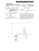
[0052] Reference is now made to FIG. 6, which illustrates one way in which the gesture recognition logic 385 executed by the controller 308 can allow the camera device 300 to interpret gestures performed by a human subject 501 visible in the target scene to modify framing conditions or other attributes associated with the camera device 300. As described above, the subject 501 can select framing conditions associated with an image captured by the camera device 300. In the depicted example, the subject 501 can point with an index finger to indicate the top of the image frame as well as point to the ground to indicate that the subject 501 desires that the image frame extend to the ground beneath the subject 501.
[0053] The subject 501 can also perform various other gestures that can be recognized by the gesture recognition logic 385 and linked to certain actions within the camera device. For example, as noted above, the subject 501 can perform a gesture identifying a focus point in the current framing of the image, and the gesture recognition logic 385 can adjust the focus point of the lens system 301 in response. The subject 501 can perform another gesture that can be linked with changing the depth of field setting of the camera device 300, which the gesture recognition logic 385 can identify and act on. The subject 501 can perform gestures that select various modes in which the camera device 300 can be placed by performing one or more gestures. For example, a gesture can be linked to selection of a still image capture mode while another gesture can be linked to selection of a video capture mode. As another example, the subject 501 can select a scene mode associated with the camera device 300, such as a landscape scene mode, a portrait scene mode, a fast-motion video capture mode, a high quality video capture mode, and any/or other mode that can be associated with the camera device 300.
[0054] The gesture recognition logic 385 also recognizes a gesture that can be linked to selection of an aspect ratio associated with image or video capture. The subject 501 can perform a gesture that also selects what or where the subject 501 would like to capture in an image or video captured by the camera device 300. In one embodiment, the camera device 300 can be configured with a wide, high resolution field of view of the target scene, and the gesture recognition logic 385 can allow the subject 501 to perform a gesture that selects a subset of the field of view as the current framing of the image. The gesture recognition logic 385 can modify the current framing of the image without altering the zoom level associated with the lens system 301. In this way, the gesture recognition logic 385 can quickly modify framing conditions without having to modify a zoom level of the lens system 301. As another example, the image sensor 302 can comprise an array of imager elements or image sensors, and the gesture recognition logic 385 can modify framing conditions by selecting a subset of the array of imager elements. The gesture recognition logic 385 can allow other adjustments to be made via gestures performed by a subject 501. For example, optical zoom adjustments, mechanical panning adjustments (e.g., when the camera device 300 is attached to a motorized tripod), flash settings (e.g., on, off, automatic, etc.), and other camera device 300 settings as can be appreciated can be linked to a gesture performed by the subject 501, which can be recognized by the gesture recognition logic 385, which can in turn cause the requested adjustment to be made.
[0055] The gesture recognition logic 385 can also allow the subject 501 to perform gestures that alter framing feedback provided by the framing feedback logic 321. In the depicted example, the display projection logic 376 causes the MEMs pico-projector 324 of the camera device 300 to project a representation of the current framing of the image or video onto the ground within or near the target scene. The gesture recognition logic 385 also recognizes gestures that allow the user to modify where the projection appears. For example, the user can perform a gesture that causes the projection to appear on a background, on a surface behind the camera device 300, or on any other surface within or near the target scene. The gesture recognition logic 385 can also recognize a gesture performed by the subject 501 that is linked to changing the size and/or orientation of the projection.
[0056] FIG. 6 also illustrates how the display projection logic 376 can provide framing feedback to a subject 501 in a target scene to which the lens system 301 of the camera device 300 is aimed. In the depicted example, the display projection logic 376 can cause the MEMS pico-projector 324 to generate a projection 621 of a current framing of an image, or the current field of view of the camera device, on a surface outside the housing of the camera device 300 that is visible from a position in the target scene by the subject 501. In the depicted example, the projection 621 is projected towards a ground level near the target scene such that it is visible by the subject 501. In some embodiments, the projection 621 generated by the MEMS pico-projector 324 can also include a textual and/or graphics overlay with additional information such as an indicator showing whether image and/or video capture is underway, textual information regarding camera device 300 settings (e.g., aperture, shutter speed, scene mode, etc.), whether there is excessive motion within the camera device 300 hindering image or video capture, or any other information that might be relevant to the subject 501 that is related to framing conditions.
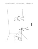
[0057] Reference is now made to FIG. 7, which continues the example of FIG. 6. FIG. 7 illustrates how the projection-illumination subsystem 323 can, via the MEMS pico-projector 324, project the current framing of an image in various directions and on various surfaces such that it is visible from a position in the target scene. In the depicted example, the camera device 300 is equipped with an additional MEMS pico-projector 324 that is positioned on an opposing side of the camera device 300 housing. This allows the projection 621 to be cast on any number of surfaces in any number of directions.
[0058] Additionally, the gesture recognition logic 385 can allow the subject 501 to perform a gesture to alter the positioning of the projection 621. For example, in FIG. 7, the subject 501 has performed a gesture to cause the gesture recognition logic 385 to request that the display projection logic 376 change a surface upon which the projection 621 is cast. The display projection logic 376 can also adjust and/or introduce skew into the projection 621 generated by the MEMS pico-projector 324 in the event that a surface upon which the projection 621 is cast is not normal to the camera device 300, thereby yielding a proportional rectangular image projected on the surface. Such an adjustment can be manually directed with user inputs via an input device integrated within the camera device 300 or via gestures captured by the camera device, electronically via analysis of a projection which at least in part falls within the field of view of the image sensor and/or a second imager, and/or via triangulation based infrared emitter detectors
[0059] FIG. 7 also illustrates how a gesture performed by the subject 501 can cause the gesture recognition logic 385 to alter the current framing of the image as directed by the subject 501. In the depicted example, the subject 501 performs a gesture indicating how a zoom level of the lens system 301 can be changed or how an image can be cropped by the controller 208.
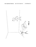
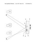
[0060] Reference is now made to FIG. 8, which illustrates an example of an alternative way in which the framing feedback logic 321 can generate framing feedback. In the depicted example, the framing feedback logic 321 can direct the projection-illumination subsystem 323 to generate a frustum of light 701 that is visible from a position within the target scene. Additionally, because the frustum of light 701 is generated by a holographic optical element and/or a laser system, it can be configured so that it is substantially invisible from a position outside the target scene with the exception of a background on which the light falls and assuming there is minimal debris or particulate matter in the air surrounding the target scene. In this way, a subject 501 can know if he or she is in the target scene based upon whether he or she can see the frustum of light 701 and/or whether he or she is within the frustum of light 701.
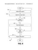
[0061] Referring next to FIG. 9, shown is a flowchart that provides one example of the operation of a portion of the video capture logic 315 according to various embodiments. It is understood that the flowchart of FIG. 9 provides merely an example of the many different types of functional arrangements that may be employed to implement the operation of the portion of the video capture logic 315 as described herein. As an alternative, the flowchart of FIG. 9 may be viewed as depicting an example of steps of a method implemented in an camera device 104 according to one or more embodiments.
[0062] First, in box 801, the video capture logic 315 initiates video capture according to a requested frame rate. In box 803, the video capture logic 315 can determine, via one or more motion sensors 313, a level of motion, movement and/or vibration of the camera device 300. In box 805, the video capture logic 315 can determine whether the level of movement of the camera device 300 exceeds a threshold. As noted above, such a threshold can be a threshold that is relative to movement during capture of a current video or an absolute threshold. In box 807, the video capture logic 315 can skip capture of a video frame if the movement level exceeds the threshold. In box 809, the video capture logic can determine whether capture of a video frame should be forced to comply with a requested frame rate, even if movement levels of the camera device 300 exceed the threshold. In box 811, the video frame can be captured.
[0063] Embodiments of the present disclosure can be implemented in various devices, for example, having a processor, memory, and image capture hardware. The logic described herein can be executable by one or more processors integrated with a device. In one embodiment, an application executed in a computing device, such as a mobile device, can invoke API's that provide the logic described herein as well as facilitate interaction with image capture hardware. Where any component discussed herein is implemented in the form of software, any one of a number of programming languages may be employed such as, for example, processor specific assembler languages, C, C++, C#, Objective C, Java, Javascript, Perl, PHP, Visual Basic, Python, Ruby, Delphi, Flash, or other programming languages.
[0064] As such, these software components can be executable by one or more processors in various devices. In this respect, the term "executable" means a program file that is in a form that can ultimately be run by a processor. Examples of executable programs may be, for example, a compiled program that can be translated into machine code in a format that can be loaded into a random access portion of memory and run by a processor, source code that may be expressed in proper format such as object code that is capable of being loaded into a random access portion of the memory and executed by the processor, or source code that may be interpreted by another executable program to generate instructions in a random access portion of the memory to be executed by the processor, etc. An executable program may be stored in any portion or component of the memory including, for example, random access memory (RAM), read-only memory (ROM), hard drive, solid-state drive, USB flash drive, memory card, optical disc such as compact disc (CD) or digital versatile disc (DVD), floppy disk, magnetic tape, or other memory components.
[0065] Although various logic described herein may be embodied in software or code executed by general purpose hardware as discussed above, as an alternative the same may also be embodied in dedicated hardware or a combination of software/general purpose hardware and dedicated hardware. If embodied in dedicated hardware, each can be implemented as a circuit or state machine that employs any one of or a combination of a number of technologies. These technologies may include, but are not limited to, discrete logic circuits having logic gates for implementing various logic functions upon an application of one or more data signals, application specific integrated circuits having appropriate logic gates, or other components, etc. Such technologies are generally well known by those skilled in the art and, consequently, are not described in detail herein.
[0066] The flowchart of FIG. 9 shows the functionality and operation of an implementation of portions of a camera device according to embodiments of the disclosure. If embodied in software, each block may represent a module, segment, or portion of code that comprises program instructions to implement the specified logical function(s). The program instructions may be embodied in the form of source code that comprises human-readable statements written in a programming language or machine code that comprises numerical instructions recognizable by a suitable execution system such as a processor in a computer system or other system. The machine code may be converted from the source code, etc. If embodied in hardware, each block may represent a circuit or a number of interconnected circuits to implement the specified logical function(s).
[0067] Although the flowchart of FIG. 9 shows a specific order of execution, it is understood that the order of execution may differ from that which is depicted. For example, the order of execution of two or more blocks may be scrambled relative to the order shown. Also, two or more blocks shown in succession in FIG. 9 may be executed concurrently or with partial concurrence. Further, in some embodiments, one or more of the blocks shown in FIG. 9 may be skipped or omitted. In addition, any number of counters, state variables, warning semaphores, or messages might be added to the logical flow described herein, for purposes of enhanced utility, accounting, performance measurement, or providing troubleshooting aids, etc. It is understood that all such variations are within the scope of the present disclosure.
[0068] Also, any logic or application described herein that comprises software or code, such as the framing feedback logic 321 and/or the video capture logic 315 can be embodied in any non-transitory computer-readable medium for use by or in connection with an instruction execution system such as, for example, a processor in a computer device or other system. In this sense, the logic may comprise, for example, statements including instructions and declarations that can be fetched from the computer-readable medium and executed by the instruction execution system. In the context of the present disclosure, a "computer-readable medium" can be any medium that can contain, store, or maintain the logic or application described herein for use by or in connection with the instruction execution system. The computer-readable medium can comprise any one of many physical media such as, for example, magnetic, optical, or semiconductor media. More specific examples of a suitable computer-readable medium would include, but are not limited to, magnetic tapes, magnetic floppy diskettes, magnetic hard drives, memory cards, solid-state drives, USB flash drives, or optical discs. Also, the computer-readable medium may be a random access memory (RAM) including, for example, static random access memory (SRAM) and dynamic random access memory (DRAM), or magnetic random access memory (MRAM). In addition, the computer-readable medium may be a read-only memory (ROM), a programmable read-only memory (PROM), an erasable programmable read-only memory (EPROM), an electrically erasable programmable read-only memory (EEPROM), or other type of memory device.
[0069] It should be emphasized that the above-described embodiments of the present disclosure are merely possible examples of implementations set forth for a clear understanding of the principles of the disclosure. Many variations and modifications may be made to the above-described embodiment(s) without departing substantially from the spirit and principles of the disclosure. All such modifications and variations are intended to be included herein within the scope of this disclosure and protected by the following claims.
User Contributions:
Comment about this patent or add new information about this topic:
| People who visited this patent also read: | |
| Patent application number | Title |
|---|---|
| 20160132145 | DEVICE HAVING MULTI-LAYERED TOUCH SENSITIVE SURFACE |
| 20160132144 | TOUCH SCREEN, DISPLAY DEVICE AND MANUFACTURING METHOD THEREOF USABLE FOR REALIZING 3D DISPLAY |
| 20160132143 | OPTICAL TOUCH MODULE AND TOUCH DETECTING METHOD THEREOF |
| 20160132142 | TOUCH PANEL AND MANUFACTURING METHOD THEREOF |
| 20160132141 | METHOD FOR MANUFACTURING HYBRID TRANSPARENT ELECTRODE AND HYBRID TRANSPARENT ELECTRODE |
Images included with this patent application:
 |  |
 |  |
 |  |
 |  |
 |  |
 |  |
| Similar patent applications: | |
| Date | Title |
|---|---|
| 2013-05-09 | Entry control point device, system and method |
| 2013-05-16 | Videometric systems and methods for offshore and oil-well drilling |
| 2012-03-08 | 3d camera system and method |
| 2012-07-19 | Mobile microphone system and method |
| 2013-02-28 | Mobile energy audit system and method |
| New patent applications in this class: | |
| Date | Title |
|---|---|
| 2022-05-05 | Integrated high-speed image sensor and operation method thereof |
| 2022-05-05 | Image capturing apparatus capable of recognizing voice command, control method, and recording medium |
| 2022-05-05 | Intelligent flash intensity control systems and methods |
| 2022-05-05 | Polarimetric imaging camera |
| 2019-05-16 | Image processing device, image processing method, and image processing system |
| New patent applications from these inventors: | |
| Date | Title |
|---|---|
| 2017-06-15 | Computing system supporting online purchases |
| 2016-05-12 | Integrated wireless resonant power charging and communication channel |
| 2016-03-17 | Media processing system supporting personal network activity indication exchange |
| 2016-02-04 | System and method providing location based wireless resource identification |
| 2015-12-31 | Social processing member offering fixed and intelligent services |
| Top Inventors for class "Television" | |
| Rank | Inventor's name |
|---|---|
| 1 | Canon Kabushiki Kaisha |
| 2 | Kia Silverbrook |
| 3 | Peter Corcoran |
| 4 | Petronel Bigioi |
| 5 | Eran Steinberg |